Power cables

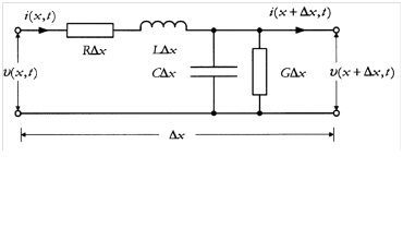
Fig. 3 Equivalent circuit for incremental section of two-conductor line
The power losses in a cable occur due to a variety of reasons. They may be caused by the conductor current passing through the resistance of the conductor - conductor loss (also sometimes called the copper loss on account of the fact that conductors were mainly made out of copper), dielectric losses caused by the voltage across the insulation, sheath losses caused by the induced currents in the sheath, and intersheath losses caused by circulating currents in loops formed between sheaths of different phases. The dielectric loss is voltage dependent, while the rest is current dependent. Power losses affect not only the efficiency of the energy transport, but also the heating of the cable, which in turns affects the thermal behavior and resistance.
As it is well known, power cables spread paths of conducted disturbances when they are feed by means of power converter. For instance, modern IGBT-based converters have modulation frequencies in the range of 2 to 20 kHz with typical switching times of 50 ns or about 13 V/ns for a 460 V system. These operating conditions induce high voltage variations (dv/dt) which in turns excite the parasitic elements of the cables and mats. Regarding to the mat side the problems become much more severe if the overstresses can initiate or enhance partial discharge (PD) activity.
On the other hand, high frequency parasitic currents are induced, which are propagated through the system by the power cables.
Share: